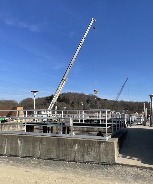
September 27, 2024The Pine Creek Wastewater Treatment Facility in Gibsonia, Pennsylvania, is undergoing upgrades to modernize its operations, originally established in the…
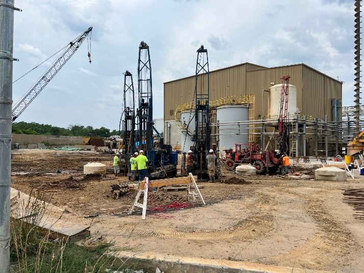
 July 1, 2024The Kyger Creek Power Plant is located in Cheshire, Ohio (Gallia County) and began servicing the area in 1955. It…
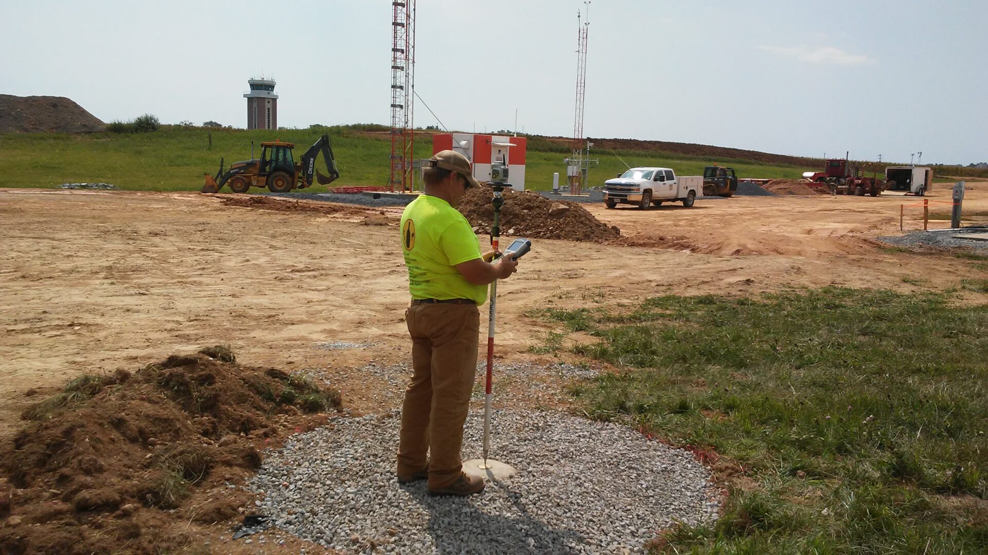
 May 13, 2020By: Cyndi Powell and Jon Taylor Triad survey was tasked with the unique challenge of establishing a True North survey…
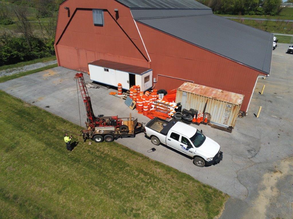
 May 6, 2020Triad Engineering, Inc. recently introduced drone technology to supplement some of our existing service offerings. This includes topographic and aerial…
 April 24, 2020By: Ben Campbell, PE and Carol Phillips, Senior Scientist Selecting a right of way (ROW) for linear projects such as…
 March 27, 2020By: Billie Swailes, PECivil Practice Leader In October of 2019, a water leak was discovered at the Keedysville Springhouse, a…
- August 1, 2019Recently a report surfaced on LinkedIn regarding the INOVA Schar Cancer Institute in Fairfax, VA. This report indicates that the…
- May 21, 2019Triad Engineering, Inc. was pleased to work with Brechbill & Helman Construction Company, Inc. of Chambersburg PA on a construction…